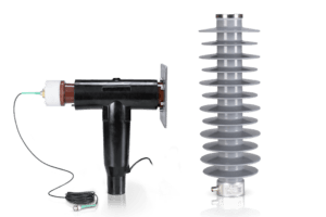
![Ohmic Voltage Sensor [+], Indisol](https://indisol.pt/wp-content/uploads/2025/09/1-768x512.png)
![Capacitive Voltage Sensor [+], Indisol](https://indisol.pt/wp-content/uploads/2025/09/4-768x512.png)
![Resistive Capacitive Voltage Sensor [+], Indisol](https://indisol.pt/wp-content/uploads/2025/09/5-768x512.png)
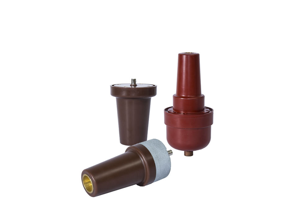
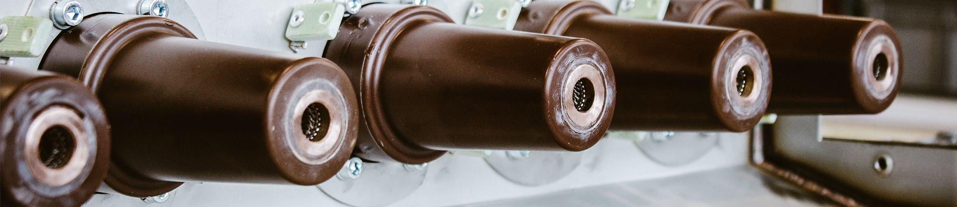
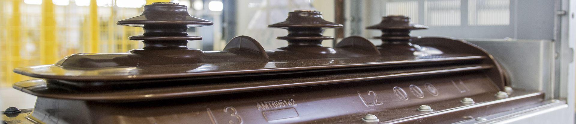
A medium voltage sensor does the job of an instrument transformer with a voltage divider cast into epoxy: the same insulator that holds the conductor also delivers a low voltage image of what is on it. Indisol designs and manufactures them for 12 kV to 72 kV networks, in three divider technologies, with measured value deviation down to 0.2%.
Choosing between the three is not really a question of voltage — all three cover the medium voltage range. It is a question of what the signal has to do. A protection relay or a power quality analyser needs an accurate, linear image of the waveform. A voltage detecting system needs to know reliably whether the busbar is live. A hybrid does both from one part.
Because the divider is cast into the insulator, there is no saturable core anywhere in the part. That is the practical reason these sensors cannot fall into ferroresonance, and it is also why they are smaller and lighter than the transformer they replace instead of being one more component in the panel.
Every part is engineered to your interface rather than picked from a catalogue, so the housing, the height and diameter, the fixing centres and the secondary connector follow your switchgear.
Not sure which of the three you need? Send us the operating voltage, the accuracy class and what the signal feeds — a protection relay, a monitoring system, or voltage indication — and we will tell you which technology fits.
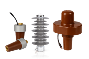
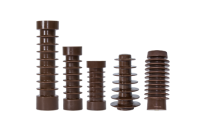
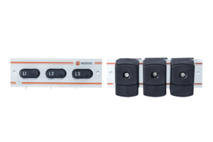
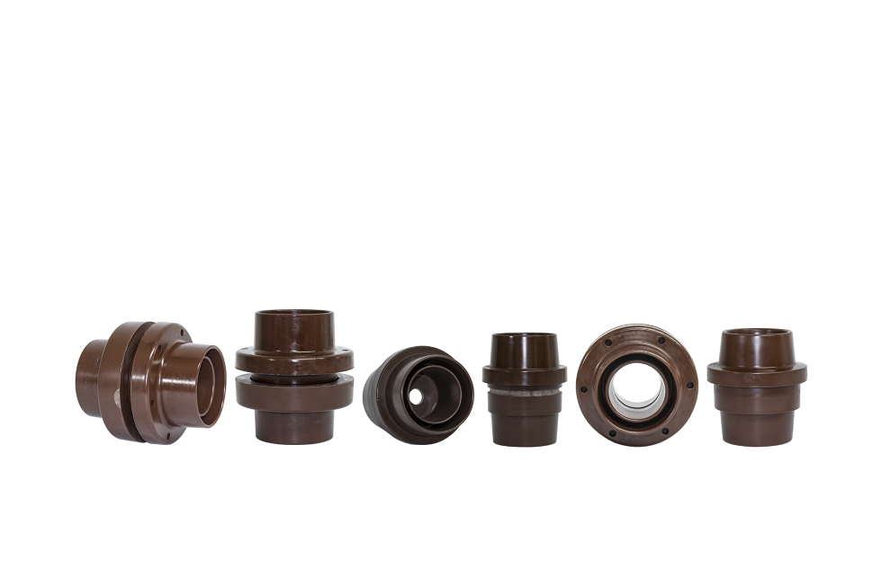
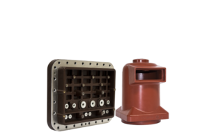
Ohmic, capacitive and resistive-capacitive medium voltage sensors, cast in epoxy by Indisol
What you get instead of an instrument transformer
Size and weight. A cast divider is a fraction of the volume of a wound transformer of the same rating, and it is the insulator as well — so it takes the place of a component rather than asking for space the panel does not have.
No ferroresonance. Ferroresonance needs a saturable magnetic core to resonate against the network capacitance. A divider has no core, so the failure mode is removed rather than damped.
Linearity and bandwidth. A wound transformer is designed around one frequency. A divider is linear by construction and holds its ratio across a wide frequency range, which is what makes harmonic and transient information usable.
Standardised interfaces. The ohmic range outputs 3.25 V through a pluggable BNC connector or an RJ45 interface, so integration with monitoring and control systems is a wiring job rather than an engineering project.
Where our sensors are used
The ranges are optimised for indoor applications. Three settings account for most of what we ship.
How a sensor gets specified
Four things settle the design. You do not need all of them to start a conversation.
Compatibility and testing
The sensor design is mechanically and electrically compatible with widely used connector sets and components, including balanced plugs, Nexans, NKT, Südkabel and TE Connectivity. Tell us what you already have in the panel.
Testing runs in house and in external laboratories under ISO 9001 and ISO 14001: industrial frequency and partial discharges to 200 kV, high voltage and current metrology, and contact resistance.
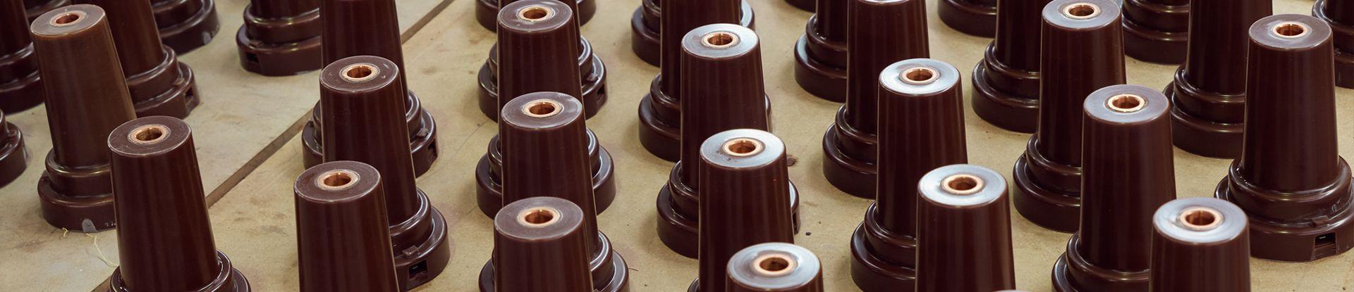
Series parts are cast by gelation under pressure at temperature, which is what keeps the divider ratio and the dielectric behaviour consistent across a whole production run. More on how we cast them.
The rest of what we cast
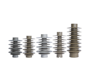
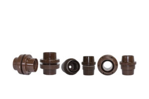
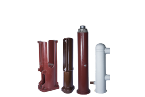
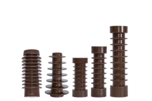
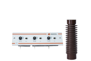
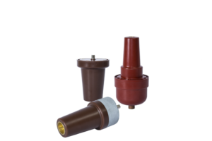
A voltage sensor is one of seven families of cast epoxy parts. Go straight to the right one.
Common questions
Tell us what the signal has to do, and we will tell you which sensor to use.
Every part we cast is engineered to a specification rather than selected from a catalogue, so you get a design proposal back, not a page number. You do not need all of the detail to start.
Request a quotation → or see how we cast them