
Need to test or specify an epoxy part for higher voltages? Our product pages give the technical detail and a route to a quotation.
More test voltage to keep pace with the market: now up to 200 kV
Power networks are asking more of their insulators, and our testing has to keep up. That is why we have raised our in-house test voltage from 150 kV to 200 kV, with a new power-frequency withstand and partial discharge test system. Cast epoxy parts are now verified at voltages well above those they will see in service, without leaving our factory.
On this page
1. Why we raised our test voltage
Demands on insulation are rising. Networks run at higher voltage classes, equipment keeps getting more compact, and customer specifications call for partial discharge tests at ever more demanding levels. A manufacturer that can only test up to a certain level ends up limiting the parts it can deliver.
We invested in the new system to keep pace with those needs. The aim is to keep testing every part in our own factory, at voltages above those it will work at, instead of relying on an external laboratory for the higher levels.
2. What a partial discharge is
A partial discharge is a small electrical discharge inside the insulation that does not bridge the two conductors. It almost always starts in a void or air bubble trapped during casting, where the electric field concentrates.
It does not cause an immediate failure. But each discharge erodes a little of the resin around the void, year after year, until the insulation breaks down. A part that passes a withstand test can still have partial discharge and fail years later, installed in a substation.
The real enemy is a void, not the voltage
That is why a withstand test is not enough. Measuring partial discharge is how internal defects that cannot be seen from the outside are found. The measurement is made to IEC 60270, the international standard that defines how apparent charge is measured and calibrated, in picocoulombs (pC). We cover the subject in more depth in our epoxy insulator reference guide.
3. What the new system brings
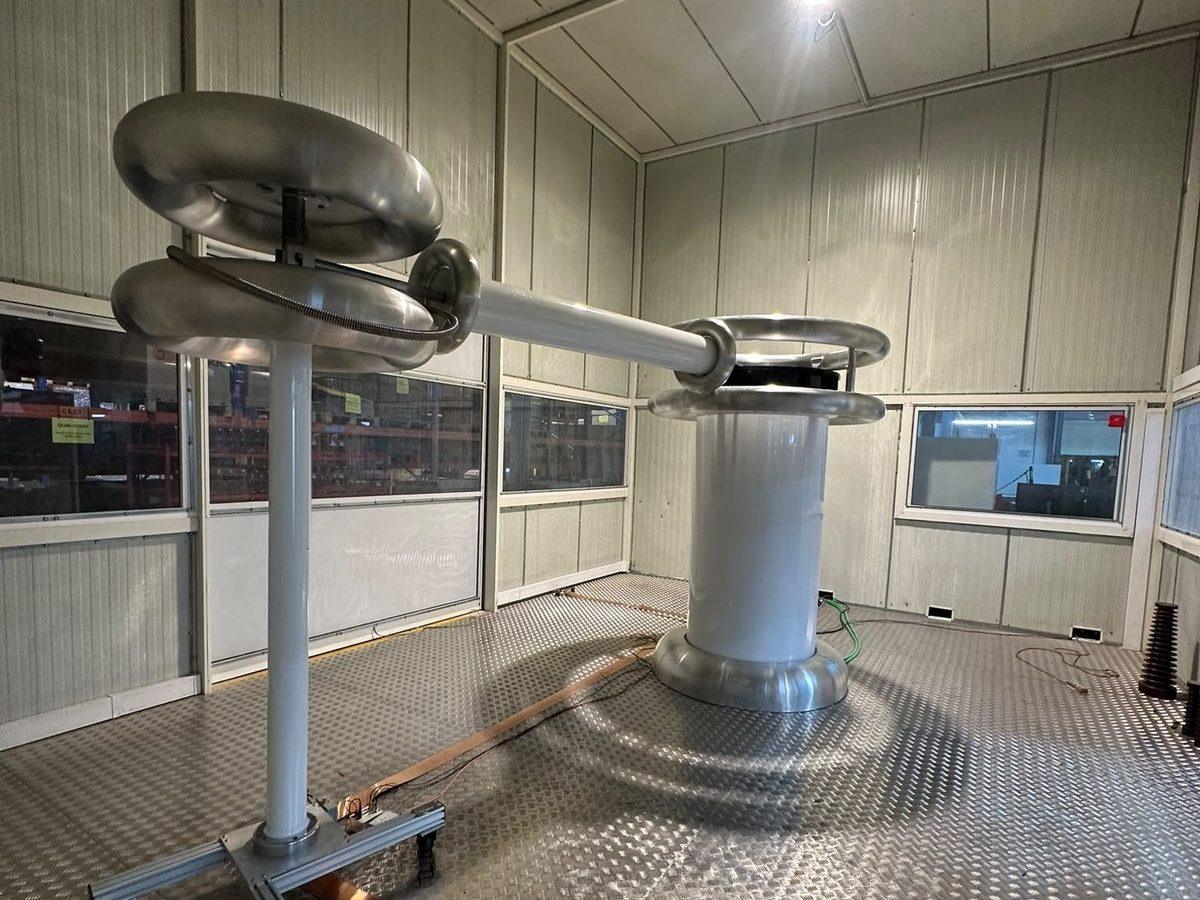
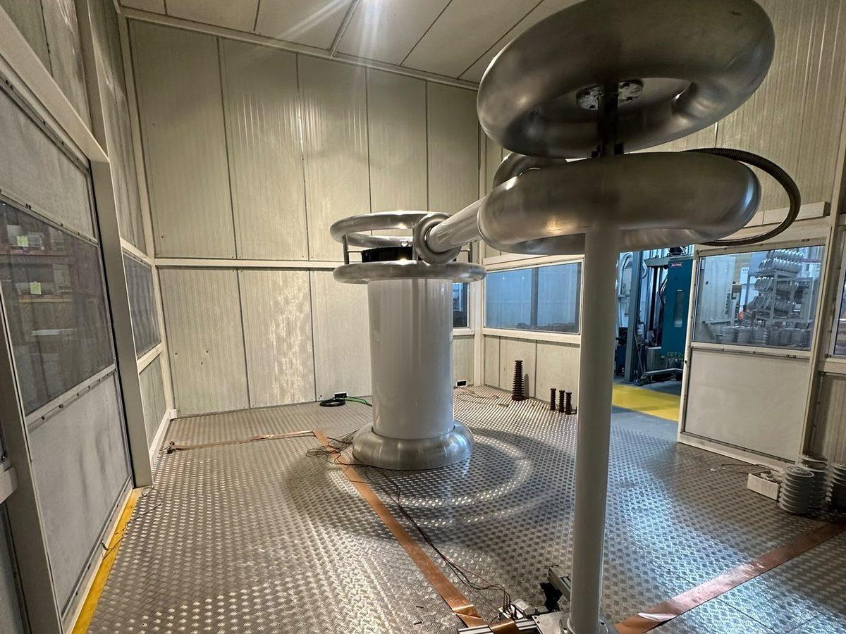
The new system has a room of its own, separate from production, operated from a control station outside it.
| Component | What it does |
|---|---|
| Test transformer | Generates the power-frequency test voltage, up to 200 kV (previously 150 kV). |
| Coupling capacitor | Carries the partial discharge signal from the part to the detector without exposing it to high voltage. |
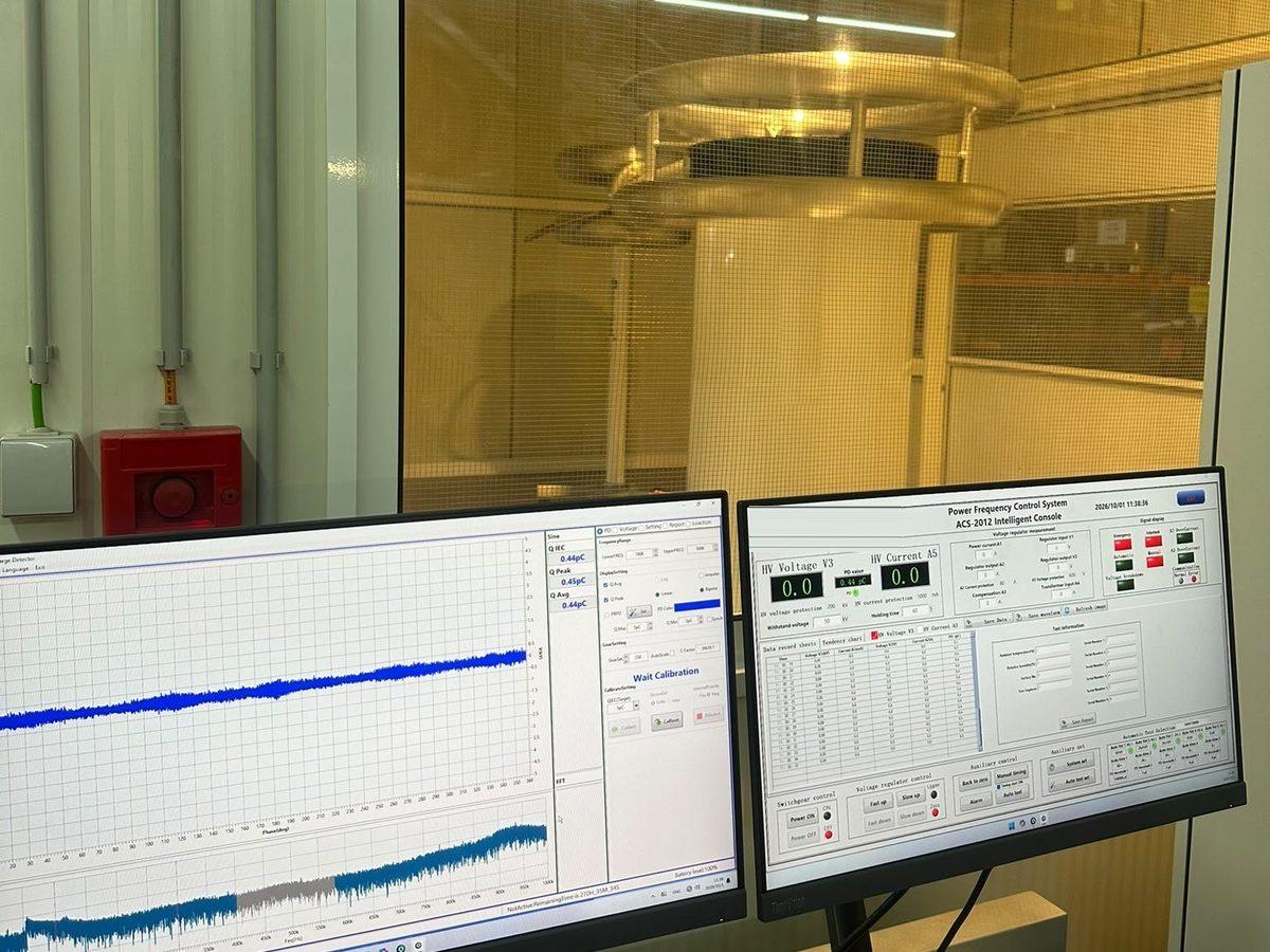
| Shielded test room | A metal floor and copper-strip earthing grid isolate the measurement from the factory’s electrical noise. With the system at rest, the background level is below 0.5 pC. |
| Control station | Direct sight into the room and an emergency stop. Logs voltage, current and discharge level throughout the test, together with room temperature and humidity. |
4. How a test runs
Every test follows the same sequence, and every step is recorded.
- Calibration. Before each test the circuit is calibrated by injecting a known charge, as IEC 60270 requires. This is what makes a pC value comparable between laboratories.
- Voltage ramp. The voltage rises in a controlled way to the test level specified for the part.
- Hold. The voltage is held for the time set in the specification while the system measures discharge continuously.
- Measurement. The partial discharge level is read in picocoulombs and compared with the acceptance limit for the part.
- Report. Voltage, current and discharge values are stored and linked to the part’s serial number.
5. What it means for customers
- Tougher specifications, met in-house. The test levels the market asks for today are tested in our own factory, without relying on external laboratories or longer lead times.
- Parts for higher rated voltages. The capacity to test bushings, support insulators and GIS components for higher voltage classes.
- Traceability. Every part has its own test record, identified by serial number.
Read more about how we design, cast and test every part on our Technology page.
Send us the part specification and the test level you need.

